Hardware Configuration
Equipment used
- For the hardware communication to be achieved the following equipment is suggested:
- USB -> Serial (RS-232) adapter
- RS-232 -> RS-485 converter
- Power cables (Power + GND)
- Jumper wires (at least 2 Female to Male)
- Breadboard (optional)
Connecting the XP3000
The serial communication with the pump was implemented using the RS-485 serial protocol.
Suggested Hardware Communication to the pump
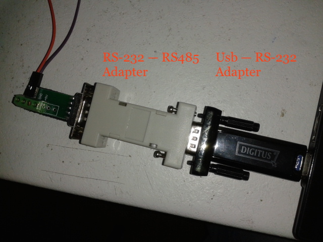
Adapters setup
The needed steps to archive a similar connection would be the following:
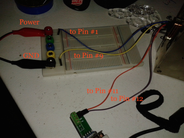
1. Connect the pump to a power supply. As described in the manual the XP3000 requires a 24VDC power supply with a current rating of at least 1.5A. As seen in hardware-conf, during the development part, the power was supplied indirectly to the pump first by running the supply cables into a breadboard and then using extra jumpers to connect to pump pins #1 (power) and #9(GND)
2. For the serial communication, you need to connect the RS-485A, RS-485B signals from the pump PCB into the RS-485+, RS-485- of the data terminal (PC) used for the communication. Take extra notice when it comes to connecting the jumpers from the serial adapter to the pump PCB corresponding pins
3. Also if the computer in use doesn’t have a serial port available, the user should use either a USB to RS-485 adapter, or combine a more commonly found USB to RS-232 with a RS-232 to RS-485 adapters
To sum it up, here is the typical RS-485 pinout for the pump [1], as it is described above
| Role | Pin No | Signal to Connect |
|---|---|---|
| Power | #1 [Power] | 24 VDC |
| #9 [GND] | Ground (of the power supply) | |
| Protocol Signals | #11 [RS-485A] | RS-485 (+) |
| #12 [RS-385B] | RS-485 (-) |
Footnotes
| [1] | For more information regarding the pump pinout consult the pump manual |